____________________________________________________________________________________
TLE 4X FAB
_____________________________________________________________________________________
Innovation · Creation · Design · Fabrication
Straight axle conversions, complete engine
conversions, TIG welding, custom suspension design, custom roll cage
fabrication, gear setup
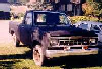
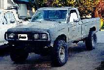
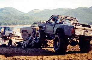
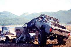
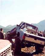
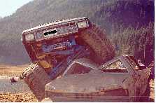
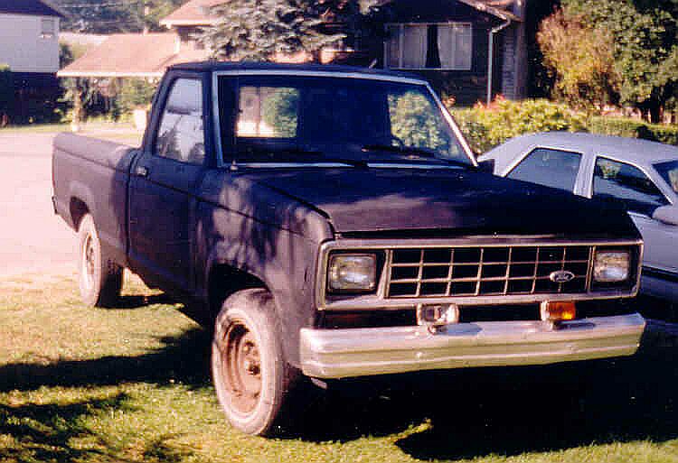
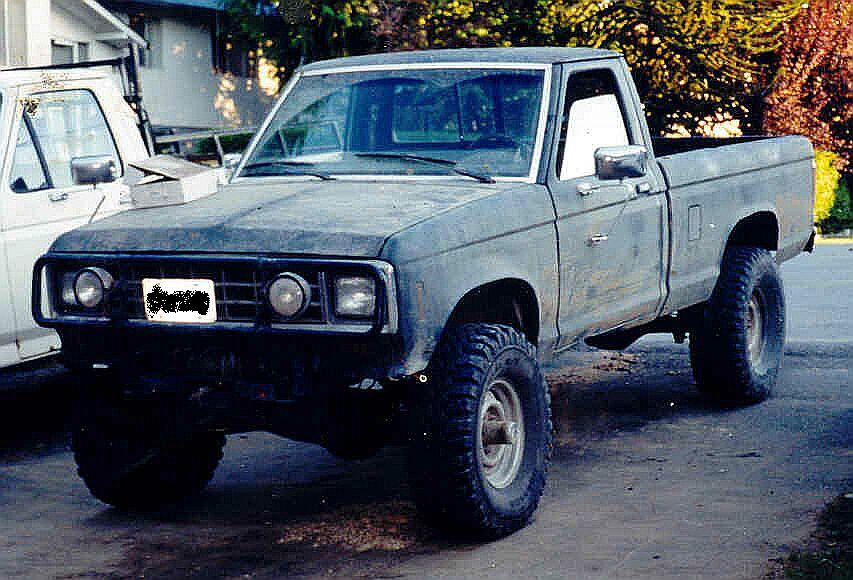
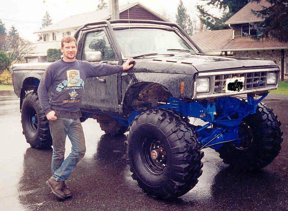
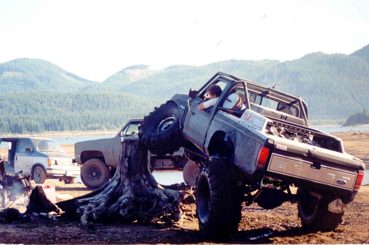
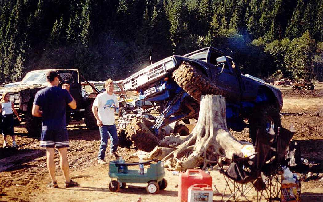
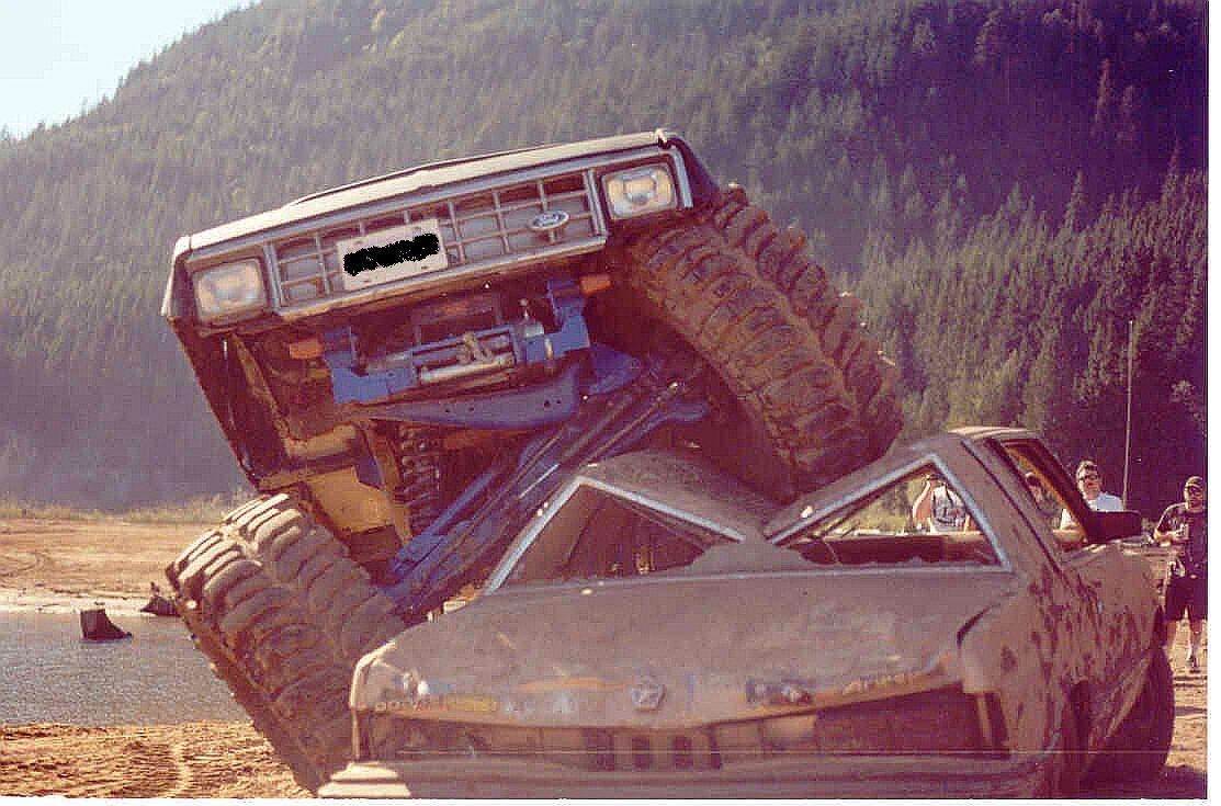
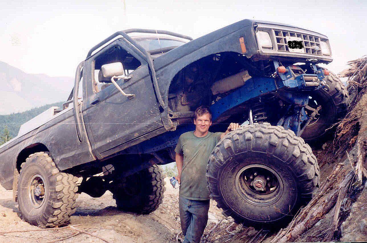
1987 Ford Ranger 2WD
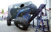
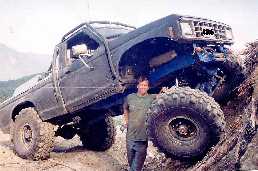
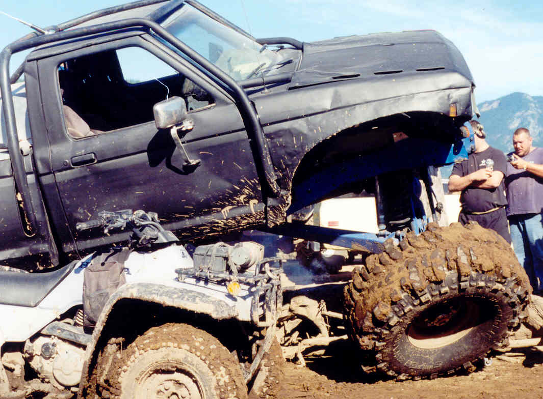
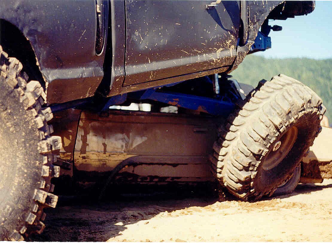
The front suspension is able to articulate to these
extremes without the lower coil spring mounts separating from the front
axle. In other words, the front axle coil springs are not designed to
separate from the front axle for added droop. A “triangle” style front coil
spring system was designed. The engine and transmission was relocated to
the middle of the truck to accommodate the front suspension designs. Larger
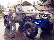
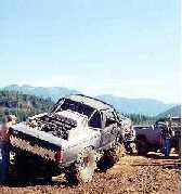
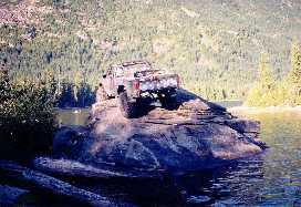
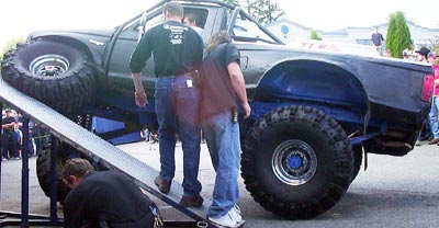
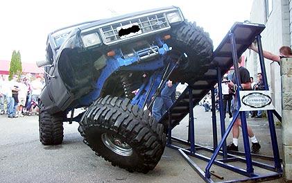
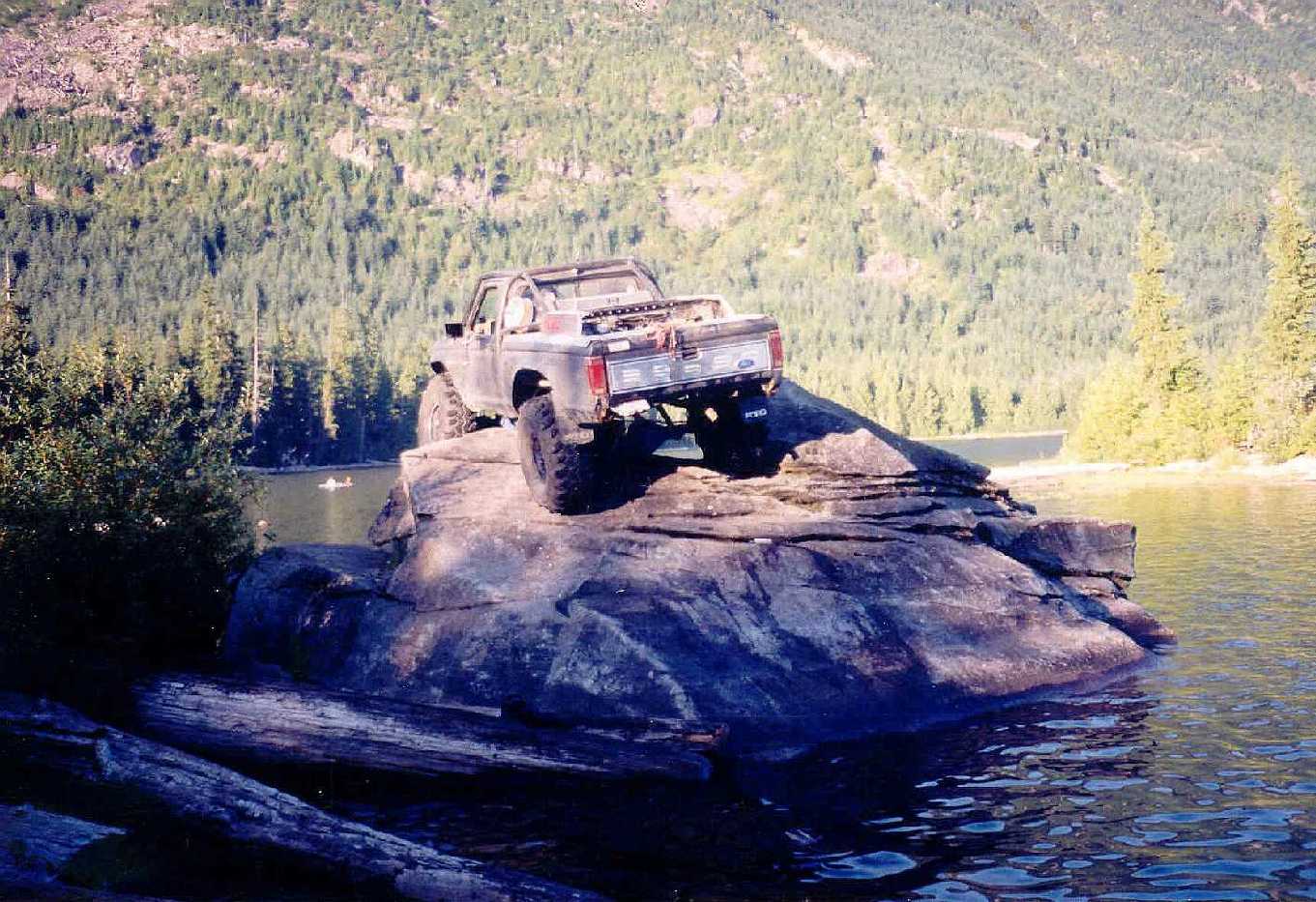
picture here. A Ford Ranger, originally a 2 wheel drive pickup,
tackling the ramp. This truck is an example of what can be achieved through
“out of the box” innovation and design. As you can see from comparing the
location of the passenger front wheel to the driver front wheel, there is
over 5 feet of front suspension travel from full droop to full compression
This truck is also a daily driver and pretty good on gas thanks to the
Triton 4.6L V8. Click
here
for larger picture.

|
|
|
|
|
Bigger
Pic |
||
|
|
TLE 4x Fab Unit #1–33167 London Ave. Mission,
B.C., Canada, V2V 4P9 604.814.0094 tle4xfab@hotmail.com |
|
|
X |
||
|
|
|
|
|
Innovation · Creation · Design · Fabrication |
|
|
|
|
|
The ideal off-road vehicle has a low
Center of Gravity (CoG) and reasonable ground clearance. A low center of
gravity is needed to reduce the likelihood of tipping over on off camber
maneuvers. Ground clearance is needed to simply avoid getting stuck. Of
course, you can’t obtain one without sacrificing the other. That is, more
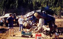
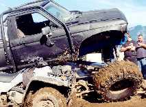
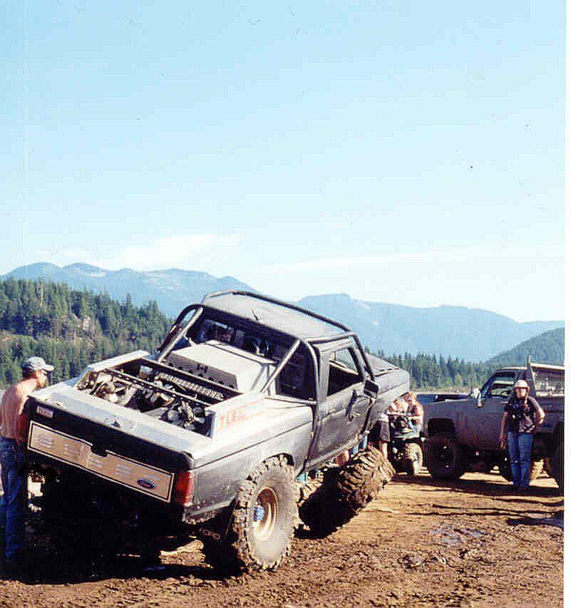
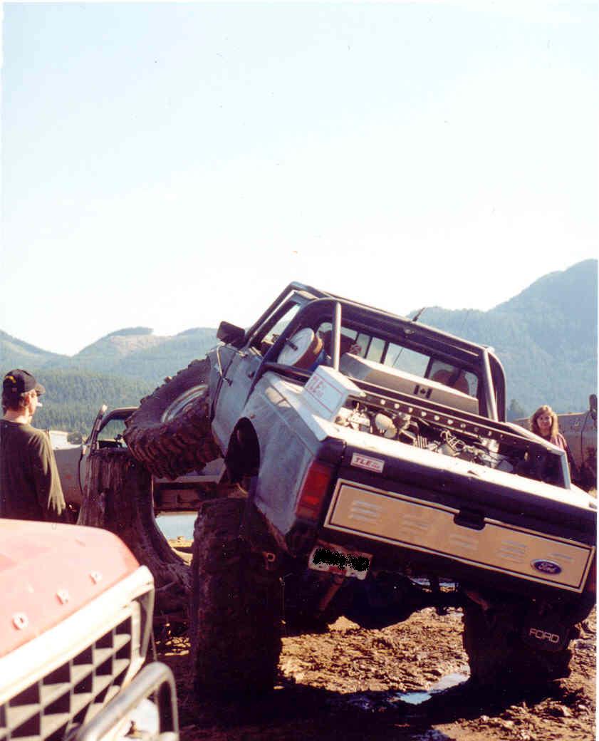
ground clearance = increased CoG and vise versa. The engine and transmission was
relocated the middle of the truck. The primary reason for relocating the
drivetrain is to make room in the engine compartment to accommodate a
long-travel front suspension design. There are several other inherent
benefits: 1. Better weight distribution, 2. Keeps the engine and transmission
out of trouble since it was mounted about 8” higher than it was in engine
compartment. 3. Serviceability is easier. There are two drivetrains ready for
this truck, a 4.6L Triton V8, and an old 460 BB. Engine swaps are extremely
easy – plenty of room and a wide open space. |
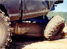
Unfortunately, relocating and
raising the engine and transmission means raising the Center of Gravity
(CoG). This is not good – especially for a vehicle designed to be a rock
crawler. So, to lower the CoG and obtain a
crawler gear ratio of thousands-to-one, a custom secondary drivetrain was
designed. The engine is mounted to the transmission which is mounted to the
transfer case, like any other 4x4. Lets call this the “primary drivetrain”.
Unlike other 4x4’s, the primary drivetrain is mounted in the middle of the
truck about 8” higher than normal. A driveshaft was fabricated to mate the
front output shaft of the primary drivetrain to the input shaft of the
secondary drivetrain which is divorce-mounted alongside the frame rail
(returning the CoG back to a favourable spot), The secondary drivetrain
thereby lowers the CoG and gives an overall crawl ratio of about 2650:1. The secondary drivetrain can be
considered one large divorced transfer case. It consists of two 4-speed
manual transmissions mounted front to back which is mounted to another
transfer case. This final transfer case powers the front and rear axles
through a custom fabricated driveshaft. Custom shift linkages have been
fabricated so all transmissions can be shifted from inside the truck. The secondary
drivetrain is mounted solidly into place near the right hand side frame rail.
It’s only link to the primary drivetrain is a single driveshaft. |